- 您现在的位置:买卖IC网 > Sheet目录536 > XC09-038PKT-RA (Digi International/Maxstream)MODEM RF 900MHZ RS232/485 W/ACC
�� �
�
�9XCite� ‐� PKG� ‐� R?� ?� RS� ‐� 232/485� ?� RF� ?� Modem� ?� –� ?� Product� ?� Manual� ?� v2.1� ?� [2007.01.04]�
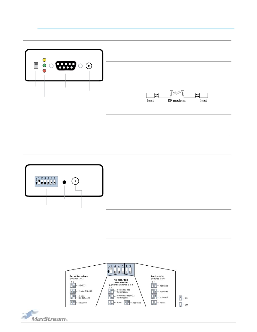
�1.3.� External� Interface�
�1-01a.� Power� Switch�
�Figure� ?� 1� ‐� 01.� Front� ?� View�
�Move� Power� Switch� to� the� ON� (up)� position� to� power� the� XCite� RS-�
�232/485� RF� Modem.�
�1-01b.� I/O� &� Power� LEDs�
�LEDs� indicate� modem� activity� as� follows:�
�Yellow� (top� LED)� =� Serial� Data� Out� (to� host)�
�Green� (middle)� =� Serial� Data� In� (from� host)�
�Red� (bottom)� =� Power/TX� Indicator� (Red� light� is� on� when�
�powered;� it� pulses� on/off� briefly� during� RF� transmission.)�
�1� ‐� 01a.� Power�
�Switch�
�1� ‐� 01b.� LEDs:�
�Yellow� ?� (top)�
�Green� ?� (middle)�
�Red� ?� (bottom)�
�1� ‐� 01c.� DB� ‐� 9�
�Serial� Port�
�1� ‐� 01d.� Power�
�Connector�
�1-01c.� DB-9� Serial� Port�
�Standard� female� RS-232� (DB-9)� DCE� connector� -� Port� is� also� used� for�
�RS-485� and� RS-422� connections.�
�1-01d.� Power� Connector*�
�7-18� VDC� Power� Connector� (Center� positive,� 5.5/2.1� mm)� -� Power�
�can� also� be� supplied� through� Pin� 9� of� the� serial� port.�
�1-02a.� DIP� Switch�
�1� ‐� 02a.� ?� DIP�
�Figure� ?� 1� ‐� 02.� Back� ?� View�
�1� ‐� 02b.� Configuration�
�Switch�
�DIP� Switch� automatically� configures� the� XCite� Module� to� operate� in�
�different� modes.� Each� time� the� RF� modem� is� powered-on,� intelligence�
�on� the� XIB-R� interface� board� programs� the� embedded� module� accord-�
�ing� to� the� positions� of� the� DIP� Switch.� [See� the� figure� below� for� DIP�
�Switch� settings.]�
�In� cases� where� AT� Commands� should� not� be� sent� each� time� the� RF�
�Modem� is� powered� on,� the� processor� must� be� disabled� by� populating�
�J7� on� the� interface� board.� [See� "Automatic� DIP� Switch� Configura-�
�tions"� section� for� more� information].�
�1-02b.� Config� (Configuration)� Switch�
�Switch�
�1� ‐� 02c.� Antenna�
�Port�
�Configuration� Switch� provides� an� alternate� way� to� enter� "AT� Com-�
�mand� Mode".� To� enter� "AT� Command� Mode"� at� the� RF� modem's�
�default� baud� rate,� hold� the� Configuration� Switch� down� while� powering�
�on� the� modem� using� the� Power� Switch.�
�1-02c.� Antenna� Port�
�This� port� is� a� 50� Ohm� RF� signal� connector� for� connecting� to� an� RPSMA�
�(Reverse� Polarity� SMA)� type� antenna.� The� RPSMA� has� threads� on� the�
�outside� of� a� barrel� and� a� male� center� conductor.�
�Figure� ?� 1� ‐� 03.� DIP� ?� Switch� ?� Settings�
�?� ?� 2007� ?� MaxStream,� ?� Inc.�
�发布紧急采购,3分钟左右您将得到回复。
相关PDF资料
XC0900A-03S
COUPLER 90DEG 811-1000MHZ 3DB
XC1900A-03S
COUPLER 90DEG 1700-2000MHZ 3DB
XC2401A8167R-G
IC GPS LNA 1.6GHZ USPN-4B02
XC2404A816UR-G
IC GPS LNA 1.6GHZ USP-8A01
XE112
LAMP T3-1/4 WITH XE GAS WHITE
XE1203SKC868XE2
KIT STARTER FOR XE1203 868MHZ
XE1205SKC868XE1
KIT STARTER FOR XE1205 868MHZ
XE1283I076TRLF
IC TXRX UHF LOW POWER 72-LFBGA
相关代理商/技术参数
XC09-038WNC
功能描述:射频模块 9XCite 4mW transcei e antenna 38400 bps
RoHS:否 制造商:Linx Technologies 产品:Transceiver Modules 频带:902 MHz to 928 MHz 输出功率:- 15.5 dBm to + 12.5 dBm 接口类型:UART 工作电源电压:- 0.3 VDC to + 5.5 VDC 传输供电电流:38.1 mA 接收供电电流:22.7 mA 天线连接器类型:U.FL 最大工作温度:+ 85 C 尺寸:1.15 mm x 0.63 mm x 0.131 mm
XC09-038WNI
功能描述:射频模块 9XCite 4mW transcei e antenna 38400 bps
RoHS:否 制造商:Linx Technologies 产品:Transceiver Modules 频带:902 MHz to 928 MHz 输出功率:- 15.5 dBm to + 12.5 dBm 接口类型:UART 工作电源电压:- 0.3 VDC to + 5.5 VDC 传输供电电流:38.1 mA 接收供电电流:22.7 mA 天线连接器类型:U.FL 最大工作温度:+ 85 C 尺寸:1.15 mm x 0.63 mm x 0.131 mm
XC-09-201-S
制造商:FLOYD BELL 功能描述:Alarm, Piezoelectric, 82 dBA to 103 dBA @ 2 Ft.,Extra Loud Continuous, 30-120VAC
XC-09-212-S
制造商:FLOYD BELL 功能描述:EXTRA LOUD CONTINUOUS, PANEL MOUNT CASE AND QUICK CONNECT BLADES WITH SCREWS TER
XC-09-212-SR
制造商:FLOYD BELL 功能描述:Alarm, Piezoelectric, 82 dBA to 103 dBA @ 2 Ft., Extra Loud Continuous, 2-12VDC
XC-09-212-W
制造商:FLOYD BELL 功能描述:EXTRA LOUD CONTINUOUS; PANEL MOUNT CASE AND WIRES TERMINATION
XC-09-301-S
制造商:FLOYD BELL 功能描述:Alarm, Piezoelectric, 82 dBA to 103 dBA @ 2 Ft.,Extra Loud Continuous,130-220VAC
XC-09-330-Q
制造商:FLOYD BELL 功能描述:EXTRA LOUD CONTINUOUS; PANEL MOUNT CASE AND QUICK CONNECT BLADES TERMINATION